- 您现在的位置:买卖IC网 > Sheet目录255 > T525D337M006ATE040 (Kemet)CAP TANT 330UF 6.3V 20% 2917
KEMET Organic Capacitor (KO-CAP) – T525 125°C Rated Polymer Tantalum
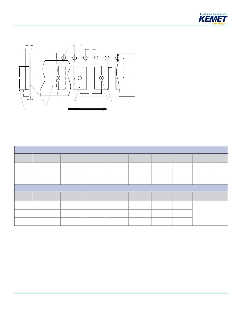
Figure 1 – Embossed (Plastic) Carrier Tape Dimensions
T
T 2
?Do
P 2
Po
[10 pitches cumulative
tolerance on tape ± 0.2 mm]
E 1
Ao
F
B 1
Ko
Bo
E 2
W
S 1
P 1
T 1
?D 1
User Direction of Unreeling
Center Lines of Cavity
Cover Tape
B 1 is for tape feeder reference only,
including draft concentric about B o .
Embossment
For cavity size,
see Note 1 Table 4
Table 4 – Embossed (Plastic) Carrier Tape Dimensions
Metric will govern
Constant Dimensions — Millimeters (Inches)
Tape Size
8 mm
12 mm
16 mm
D 0
1.5 +0.10/-0.0
(0.059 +0.004/-0.0)
D 1 Minimum
Note 1
1.0
(0.039)
1.5
(0.059)
E 1
1.75 ±0.10
(0.069 ±0.004)
P 0
4.0 ±0.10
(0.157 ±0.004)
P 2
2.0 ±0.05
(0.079 ±0.002)
R Reference
Note 2
25.0
(0.984)
30
(1.181)
S 1 Minimum
Note 3
0.600
(0.024)
T Maximum T 1 Maximum
0.600 0.100
(0.024) (0.004)
Tape Size
8 mm
12 mm
16 mm
Pitch
Single (4 mm)
Single (4 mm) &
Double (8 mm)
Triple (12 mm)
B 1 Maximum
Note 4
4.35
(0.171)
8.2
(0.323)
12.1
(0.476)
Variable Dimensions — Millimeters (Inches)
E 2 Minimum F P 1 T 2 Maximum
6.25 3.5 ±0.05 4.0 ±0.10 2.5
(0.246) (0.138 ±0.002) (0.157 ±0.004) (0.098)
10.25 5.5 ±0.05 8.0 ±0.10 4.6
(0.404) (0.217 ±0.002) (0.315 ±0.004) (0.181)
14.25 5.5 ±0.05 8.0 ±0.10 4.6
(0.561) (0.217 ±0.002) (0.315 ±0.004) (0.181)
W Maximum
8.3
(0.327)
12.3
(0.484)
16.3
(0.642)
A 0 , B 0 & K 0
Note 5
1. The embossment hole location shall be measured from the sprocket hole controlling the location of the embossment. Dimensions of embossment location and
hole location shall be applied independent of each other.
2. The tape, with or without components, shall pass around R without damage (see Figure 5).
3. If S 1 < 1.0 mm, there may not be enough area for cover tape to be properly applied (see EIA Standard 481–D, paragraph 4.3, section b).
4. B 1 dimension is a reference dimension for tape feeder clearance only.
5. The cavity defi ned by A 0 , B 0 and K 0 shall surround the component with suffi cient clearance that:
(a) the component does not protrude above the top surface of the carrier tape.
(b) the component can be removed from the cavity in a vertical direction without mechanical restriction, after the top cover tape has been removed.
(c) rotation of the component is limited to 20° maximum for 8 and 12 mm tapes and 10° maximum for 16 mm tapes (see Figure 2).
(d) lateral movement of the component is restricted to 0.5 mm maximum for 8 mm and 12 mm wide tape and to 1.0 mm maximum for 16 mm tape (see Figure 3).
(e) see Addendum in EIA Standard 481–D for standards relating to more precise taping requirements.
? KEMET Electronics Corporation ? P.O. Box 5928 ? Greenville, SC 29606 (864) 963-6300 ? www.kemet.com
T2017_T525 ? 2/3/2014
11
发布紧急采购,3分钟左右您将得到回复。
相关PDF资料
T620162004DN
SCR PHASE CTRL MOD 1600V 200A
T68-1/M
TERMINAL MINIWRAP .042" GOLD
T6V0S5-7
TVS 260W 6.0V SOD-523
T720224504DN
SCR PHASE CTRL MOD 2200V 450A
T7H8146504DN
SCR PHASE CTRL MOD 1400V 650A
T7H8166504DN
SCR PHASE CTRL MOD 1600V 650A
T7S0186504DN
SCR PHASE CTRL MOD 1800V 650A
T820149004DH
SCR PHASE CTRL MOD 1400V 900A
相关代理商/技术参数
T525D337M006ATE040DISC
功能描述:钽质电容器-SMD聚合物 6V 330uF 20% "D" RoHS:否 制造商:Kemet 电容:33 uF 电压额定值:50 V ESR:40 mOhms 容差:20 % 工作温度范围: 外壳代码 - in:2917 外壳代码 - mm:7343 高度:4 mm 制造商库存号:X Case 系列:T543 产品: 封装:Reel
T525D337M006CH
功能描述:钽质电容器-SMD聚合物 330.UF 6.0V RoHS:否 制造商:Kemet 电容:33 uF 电压额定值:50 V ESR:40 mOhms 容差:20 % 工作温度范围: 外壳代码 - in:2917 外壳代码 - mm:7343 高度:4 mm 制造商库存号:X Case 系列:T543 产品: 封装:Reel
T525D337M006DISC
功能描述:钽质电容器-SMD聚合物 6V 330uF 20% "D" RoHS:否 制造商:Kemet 电容:33 uF 电压额定值:50 V ESR:40 mOhms 容差:20 % 工作温度范围: 外壳代码 - in:2917 外壳代码 - mm:7343 高度:4 mm 制造商库存号:X Case 系列:T543 产品: 封装:Reel
T525D337M010AHE040
制造商:KEMET 制造商全称:Kemet Corporation 功能描述:CONDUCTIVE POLYMER CHIP CAPACITORS
T525D337M010ATE040
制造商:KEMET 制造商全称:Kemet Corporation 功能描述:CONDUCTIVE POLYMER CHIP CAPACITORS
T525D337M016AHE040
制造商:KEMET 制造商全称:Kemet Corporation 功能描述:CONDUCTIVE POLYMER CHIP CAPACITORS
T525D337M016ATE040
制造商:KEMET 制造商全称:Kemet Corporation 功能描述:CONDUCTIVE POLYMER CHIP CAPACITORS
T525D337M2R5AE025
制造商:KEMET 制造商全称:Kemet Corporation 功能描述:CONDUCTIVE POLYMER CHIP CAPACITORS
